Configure UR30 for a 3 lane analogic circuit
In this tutorial you'll learn how to configure UR30 for an analogic 3 lane circuit like a wood track. Basically:
- slot car detection
- lane power control
This tutorial assumes the analogic circuit is controlled by the PC parallel port. Some other tutorials describe USB joystick or USB serial control. The procedure remains the same.
Prerequisites
The slot cars sensors and lane power supply controllers have been built and connected on parallel port as follow:
| lane
#1
color: red |
lane
#2
color: green |
lane
#3
color: yellow |
|
| slot car sensor | LPT1 - pin #10 | LPT1 - pin #12 | LPT1 - pin #13 |
| lane control | LPT1 - pin #2 | LPT1 - pin #3 | LPT1 - pin #4 |
The sensors are connected on input pins.
The controllers are connected on output pins.
Example of slot car sensor using photo diods: here
Configure circuit
Click on menu
"View" -> Configure hardware and settings" or click on toolbox
button ![]()
Select
"Circuit settings" tab: ![]()
Create a new circuit OR change an existing one => Click on "Add" to create a new circuit, OR select an existing circuit in the circuit toolbar.
Change circuit settings:
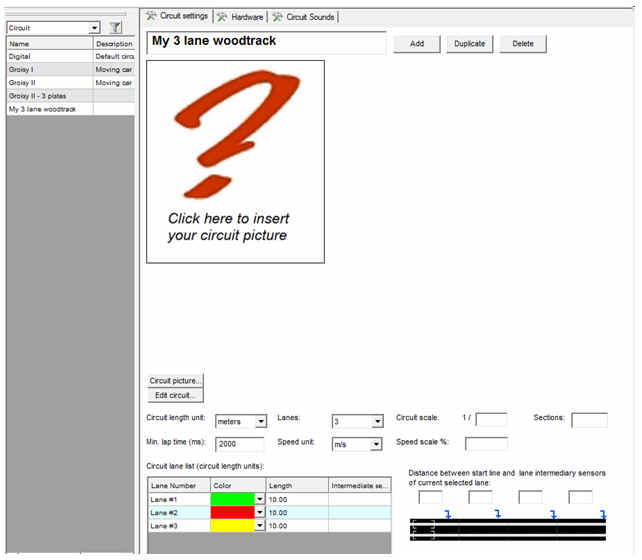
Set a circuit name: "My 3 lane wood track" in this example.
Click on "Circuit picture..." if you want to add a circuit picture.
Select the circuit units: used as unit for all lane lengths. "meters" in this example.
Number of lanes: 3
Min lap time: 2000ms. Assumes a slot car lap cannot be lower than 2s. Any lap below this limit is ignored during a heat.
Then specify in the lane table each lane length and color:
Lane #1/green is 15.2m length
Lane #2/red is 14.8m length
Lane #3/yellow is 14.5m length
These lengths are used in all heat stats. They have to be reliable.
Configure hardware
Click on "Hardware" tab: ![]()
The hardware toolbar displays all events managed by UR30. The number of events has been updated when the number of lanes has been chosen.
Let's configure the hardware events to detect slot cars and control lane power supply:
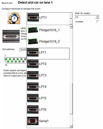
Click on "Detect slot car on lane 1". Select "LPT1" in "Configure hardware" list box, and select pin #10 in "Pin I/O" combo:
Proceed in the same way for "Detect slot car on lane 2" and"Detect slot car on lane 3".
Click on "Switch power on/off on lane 1", then select "LPT1" in "Configure hardware" list box, and select pin #2 in "Pin I/O" combo.
Proceed identically for "Switch power on/off on lane 2" and "Switch power on/off on lane 3".
The hardware event toolbar looks like this when setup is completed:
Hint: use parallel port view to check if detection works and click on squares to check outputs: