
Configure a circuit
 Click on the Hardware Settings button in the Left-bar or on the Home Page
 Or choose "Configure hardware and circuit" from the Views list in the Header Menu
 - Or press F6 on your keyboard F6
 Then click on the Circuit Settings tab
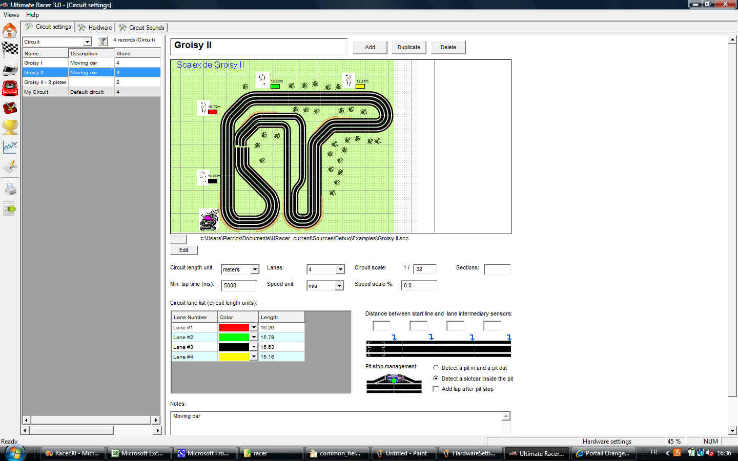
Ultimate Racer can manage as many circuits as you want, with their own settings. But only one circuit with it's corresponding settings and hardware settings can be active at one point of time.
The list on the left side of the screen displays all configured circuits. The right side displays the current selected circuit attributes.
The current selected circuit is called the "Active Circuit" or the "Current Circuit". All subsequent races or heats are always ran on the active circuit. So the settings like the number of lanes and their lenghts, or the refuel settings depend of the active circuit.
Managing a circuit
The buttons "Add", "Delete" and "Duplicate" are used to create a new circuit, delete the selected circuit or duplicate it.
A circuit deletion deletes all related races, heats and statistics.
A duplication does not duplicate any races, heats or statistics. The duplicated circuit is like a new one where settings have been copied from the original one.
Circuit picture
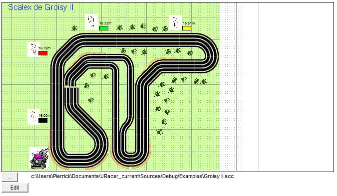
A database circuit can be attached to a picture file (gif, tif, bmp, jpg...) or a track layout (scc).
Click on the "..." to select a picture or a track layout.
Click on the "Edit" button to edit a track layout.
Circuit attributes

Circuit length unit
Units in which lengths and distances are displayed.
Lanes
Circuit number of lanes. UR manages 1, 2, 3, 4, 6 or 8 lane circuits. Caution: deleting lanes will delete all statistics attached to these lanes. The race pane is updated automatically for analogic settings.
Circuit scale
This scale factor is used to compute the real scale speed. 1:32 by default.
Sections
Number of sections in which the circuit is splitted. The number of sections is used to manage the end of heats when the heat setting option "Section" is checked.
Min lap
Threshold specific to the circuit. That’s the minimal lap duration in milliseconds acceptable for a circuit. Here, 5000 means that Ultimate Racer will not manage lap those duration is lower than 5 seconds (5 seconds = 5000 ms). All durations below this threshold will be considered as false triggers, and thus are not managed/counted.
Speed unit
Used to display all lap, driver and slot car statistics. Ultimate Racer stores all length in meters and duration in seconds. Thus these length units are used to convert lap stats from current unit into meters, then back from meters to circuit units when stats are displayed.
Available speed units
fps (feet per second)
km/h
m/s
mph
These speeds are used by the race pane to display slot car speeds.
km/h and mph use the scale factor. Thus these speeds are real scaled speeds.
m/s and fps do not use the scale factor. These speeds are circuit scaled speeds.
Ex: a slot car races one 20 meter track lane lap in 8 secs. The speeds will be displayed as follow on the race pane:
| Scale/speed | m/s | fps | km/h (real scaled) | mph (real scaled) |
| 1:24 | 20 / 8 = 2.5 m/s | 20 / (8 x 0.3048) = 8.2 fps | (20 x 24 x 3600) / (8 x 1000) = 216 km/h | (20 x 24 x 3600) / (8 x 1609.34) = 134 mph |
| 1:32 | 20 / 8 = 2.5 m/s | 20 / (8 x 0.3048) = 8.2 fps | (20 x 32 x 3600) / (8 x 1000) = 288 km/h | (20 x 32 x 3600) / (8 x 1609.34) = 179 mph |
| 1:43 | 20 / 8 = 2.5 m/s | 20 / (8 x 0.3048) = 8.2 fps | (20 x 43 x 3600) / (8 x 1000) = 387 km/h | (20 x 43 x 3600) / (8 x 1609.34) = 240 mph |
Speed scale
The speed scale is a rate applied on slot car speed to make it closer to the real speed. This parameter is optional. The speed scale is used to display a more realistic speed on the screen.
Let's say a slot car lap duration on 18m length 1:32 circuit is 10s. Then the circuit length in real world would be 32 x 18m = 576m. Corresponding speed would be 576m x 3600s / 10s = 207.4 km/h. This speed might be unrealistic on such a circuit.
So a speed scale of 40% would change this speed like this:
(576m x 3600s / 10s) x 0.4 = 82.9km/h
Example a speed scale of 70% will multiply all displayed speeds by 0.7. The default value (0) is not managed, thus no speed scale rate applied.
Notes
Edit box where you can put any comments about your circuit.
Circuit attributes
Lane List
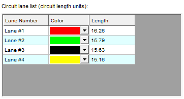
This grid displays the list of all circuit lanes and their attributes, basically their color and length (in circuit length units).
Click on a color combo-box to change it.
Type on a lane length cell to change its value.
The number of rows is modified when the number of lanes is changed, either by using the corresponding combo-box, or changing the track layout the circuit is attached to.
Starting position color
A starting position is the position a slot car starts a heat on a lane. There is one starting position per lane in an analogue circuit. Several starting position per lane in a digital circuit.
This table defines starting position colors for digital circuits.
These colors are reused everywhere in racing panes.
Pit stop
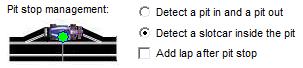
This section describes how the pit stops are managed on this circuit to refuel slot cars. This configuration is critical when the heat manages refueling.
"Detect pit & pit out": the pit stop has two sensors connected on the same hardware device pin. The first sensor (sensor #1) change starts the refueling. The second one (sensor #2) ends the refueling. Typical electrical wiring (to be adapted according to the sensor type):
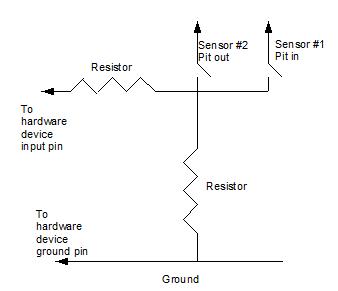
"Detect slot car inside the pit": only one sensor is connected to the hardware device pin. The refuel starts when the slot car stops on the sensor, and stops when it leaves the sensor. Typical electrical wiring (to be adapted according to the sensor type):
"Add lap after pit stop": a lap is added to the slot car heat when it leaves the pit (or when the refuel ends, that's the same thning here).
Refer to the fuel/refuel page to know how to manage refueling.
Intermediary sensor distance
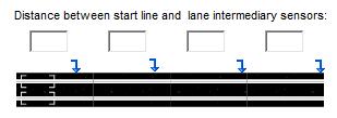
Ultimate Racer manages up to 4 intermediary sensors. Each edit box contains the distance from the start line to the sensor, in circuit units.
The electrical wiring is close from this one:
Refer to the intermediary lap time page to know how to manage intermediary lap times.
There are two intermediary sensors in this example. A first intermediary lap is triggered when sensor #1 status changes, a second intermediary lap is triggered when sensor #2 status changes.
The wiring diagram has to be changed according to the chosen sensors (photo diods, LDR, reed relay, and so on...)
Furthemore the selected race pane must contain an object displaying intermediary time statistics. Please refer to the race pane edition for the list of available intermediary time sensor race pane objects.
Header and race pane display:
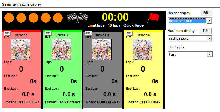
Ultimate Racer selects the best matching header and race pane according to the screen size.
The header pane is displayed above the racing panes in the race screen.
Nevertheless Ultimate Racer allows you to choose the header and pane.
To select the header or a race pane, select its definition file from corresponding combo box.
The header panes definition files are located in folder /media/racing of Ultimate Racer installation folder. They have the extension “.scc” and are prefixed with "Header". All other scc folder files are managed as race panes. The header and panes are customizable with Ultimate Racer track layout editor.
Click twice in the header pane or a race pane to open its scc file in the track layout editor.
Refer to How to customize the race view for further details.
Start Lights setup the starting line sequence. Additional starting lights sequences can be customized in the Advanced setting dialogue.